CNC Machining
Techno Titan CNC Router (Coming Soon)
The Titan Series CNC Router is manufactured using the highest quality industrial grade CNC router components with all steel construction with a 7-1/2” gantry clearance and 11-1/2” z-axis stroke so the clearance can be properly utilized. Key features include THK linear guide rails and bearings, precision helical rack and pinion with precision gear motors directly coupled to the helical pinion. The Titan series includes a 12 HP HSD high frequency automatic tool changer, with 8-postion tool rack, pneumatically operated vacuum hood that has concentrated air flow at the spindle, vacuum t-slot table controlled by a central gate valve, 10HP rotary vane vacuum pump, and pop-up pins for easy sheet alignment.
Location: Voorhees 107
Work Surface Area: 4' x 8'

Roland MDX-540 3-Axis CNC Mill [2]
The Roland MDX-540 3-Axis milling machine is a computer numerical controlled mill with a 19.68(X) x 15.74(Y) x 6.10(Z) machinable area, an operating speed of up to 295in/min, and a spindle speed of up to 12,000rpm for cutting a variety of sheets or blocks of material including foams, woods, and plastics. The Roland mills feature optional automatic tool changers to allow for multi-tool nc programs as well as an optional rotary attachment that automatically rotates to allow for 4th axis approaches at ninety degree
increments around the part.
Location: Voorhees 107
Work Surface Area: 19.6" x 15.7" x 6.1"

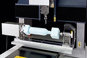
Roland ZCL-540 Rotary Axis Unit [2]
The ZCL-540 4th axis rotary attachment can be used for the 4th axis approach in addition to the default 3 axis approach of the MDX-540. this system can allow you to create multi-sided objects automatically without the need for manually flipping the part over, max envelope (4x4x11.25").
CNC MACHINING GUIDELINES
CNC machining is a subtractive fabrication technology that uses a computer numerically controlled cutting tool (end mill) to “carve” design prototypes from a variety of sheets or blocks of material including foams, woods, plastics, and metals. Though CNC machines come in a variety of forms, most are capable of simultaneous 3‐axis movement with X and Y motion controlled by the gantry and Z motion controlled by the spindle head. End mills cut along tool paths with specified linear feeds (typically measured in inches of movement per minute or in/min) and rotational speeds (typically measured in revolutions per minutes or RPC) that are determined by the cutting strategy being utilized, the size and type of the tool, and the material being machined. Though they vary widely, a typical CNC cutting strategy would include profiling, roughing, semi‐finishing, and finishing passes.
The following is a list, by no means all‐inclusive, of some basic guidelines to keep in mind when designing parts to be fabricated by CNC machining:
-
Parts to be CNC machined must be programmed using RhinoCAM, MasterCAM and other programs can be utilized but the CLT must run the gcode to make sure the program will work on the machines. RhinoCAM is a plug‐in that is available in the computer labs.
-
The maximum cutting area of the Roland CNC router is 19.68in (X) x 15.74in (Y) x 6.10in (Z).
-
The part you’re machining could be 3‐axis approachable – areas of the model that are not 3‐axis approachable are called undercuts and will be ignored by the machine. In Rhino, use Draft Angle Analysis to located any undercuts.
-
A good rule of thumb is that the entirety of your model must be visible in the Top viewport in order to be 3‐axis approachable.
-
The material being machined must be held rigid through the entire duration of the cut – this can be done mechanically with fasteners (screws, bolts, etc.), tape, or, when available, non mechanically with the suction provided by a vacuum bed.
-
In RhinoCAM use collision detection to ensure that neither the tool’s shank nor its holder is colliding with your model or your remaining material stock.
-
Special programming is required for parts which cannot be split up for 3‐axis approachability and must be cut from multiple positions.
-
Any files saved on the CNC computers must be in a folder under the current date (EX. April 21, 2017= 170421) under the Temp_files folder on the desktop. Name your original Rhino file and your post‐processed G‐code (*.nc) file using the following convention:
RHINO: Lastname_Course_Professor_Semester
GCODE: Lastname_ToolpathType_Number
